If I have a noisy process can I still use the same tuning methods? Can I get good tuning despite noise, and if not, what can I do to compensate?

Insights about tuning noisy processes.
- Open loop tuning: Noise complicates estimating deadtime and lag which will affect tuning constants. If possible a bigger step size will help. Use conservative tuning constants and speed up as needed.
- Closed loop tuning: Noise makes it difficult to establish a steady swing which makes this a very time consuming and hazardous approach. It should be avoided.
- Relay tuning: Noise makes automated tuning almost impossible. Processes with low noise can be tuned manually.
- Heuristic tuning: Noise may complicate pattern identification, however with care reasonable tuning can be achieved.
Process noise affects the open, closed and heuristic tuning methods by making it more difficult to estimate the parameters required to calculate the controller tuning constants. We are going to have to tune in the presence of noise so we need to know how noise affects tuning and what we can do about it.
Unless stated otherwise, I am using a +/-10% white noise signal in every example. This is excessive and we would normally apply some filtering before we attempted to tune a controller. This same process was used in the articles on open, closed and heuristic loop tuning (PID spotlight parts 7, 8 and 9; see links at bottom of this article) so that we can compare tuning with noise versus tuning without noise.
How noise affects open loop tuning

Figure 1 shows two open loop step tests of different sizes. As with a sticking control valve a bigger step will yield better results. It’s normal to end up with different deadtime and lag time estimates when you do multiple steps. In this case the deadtime estimate is the same for both steps, which is unusual.
The methodology remains the same. You draw a line through the steepest part of the slope and estimate deadtime (Dt) from where the line crosses the initial process variable (PV) value and the process lag (T1) from where the line reaches 63.2% of the final PV value. The problem is you must guess at the PV trajectory through the noise, which is an inherently uncertain task.
You can get a good estimate of the change in the PV if you can let the test run long enough before the controller output change (OP) and after the process lines out. If this is a slow process this may be much more difficult. Regardless, in the presence of noise open loop step tests take longer than they would without noise.
How do the results of these step tests compare with the clean test from PID spotlight part 7?
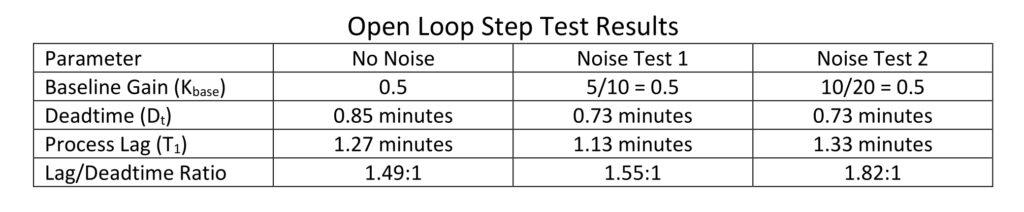
Based on Table 1, we can see that deadtime is underestimated (but it could as easily have been over) and the process lag estimated from the two tests with noise bracket the actual lag. Knowing that the estimates can be off, we can counter any possible error by using a lower controller gain and slower integral than our chosen calculation method recommends. We know that we are not going to use derivative so this doesn’t need to be calculated. Fortunately PID tuning constants do not have to be very accurate to still work, and we always have heuristic tuning to trim up the tuning to get the performance we need.
How noise affects closed loop tuning

Noise complicates setting the ultimate gain (Ku) and estimating the natural period (Pn). In Figure 2 the natural period was estimated by guessing where the process variable (PV) peak was for multiple cycles. The natural period was estimated based on the distance between four peaks. Figure 2 does not explain the effort required to determine the ultimate gain. Controller gains of 1.25 and 1.30 both resulted in what appeared to be continuous swings. A controller gain of 1.20 was clearly below the ultimate gain (contracting swing), and 1.35 was above the ultimate gain (clearly expanding). While this test doesn’t show it, it is not unusual for the peaks to randomly differ in height. When this occurs, it can be very difficult to determine the ultimate gain.
In PID spotlight part 8 we found that for this process, the ultimate gain was 1.26 and the natural period was 3.42 minutes. Based on this example we can conclude that with a fairly large noise band we can still make a reasonable estimate of ultimate gain and the natural period. However, it will likely require more effort.
How noise affects relay tuning
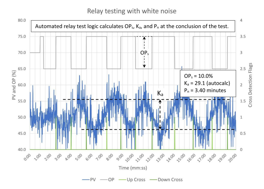
Relay testing a noisy process, especially automated testing, can be a very tricky process. The automated detection software needs additional logic to detect when the process variable (PV) crosses the setpoint (SP). The logic used in figure 3 prevents crossover detection for 60 seconds after the controller output (OP) is changed and includes a crossing detection deadband of 5% (the PV must be > 5% past the SP). Both parameters help prevent false early crossing detection. Setting these two parameters required multiple tests and increasing the controller output step size from 5 to 10%.
Regardless, I still wouldn’t trust this test. The crossover times vary between 2.75 and 4.25 minutes. Overall the estimated natural period (Pn) did match the relay test results in PID spotlight part 8 figure 4, but this is more happenstance than an indication of the reliability of the method.
The automated method grossly overestimates the swing amplitude (Ka) because it traps the very highest or lowest values at the ends of the swing. The actual swing amplitude will be approximately the captured swing amplitude minus the peak noise amplitude (in this case 20%).
Ka ~= Ka-calculated – peak noise amplitude
Ka ~= 29.1 – 20
Ka ~= 9.1
In reality the best method to estimate swing amplitude is to do it manually. In figure 3 the visually estimated maximum and minimum swing peaks are 56% and 47% for a total swing amplitude of 9%. From here we can calculate the ultimate gain.
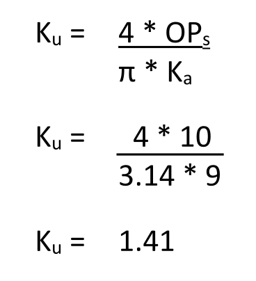
The calculated ultimate gain is 17% higher than the calculated ultimate gain from PID spotlight part 8 (1.21).
While the results here appear to be within a reasonable range of those calculated without noise, I would still avoid using these. However, this does raise the question: Can we use relay testing when there is less noise?
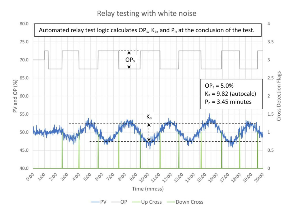
Reduced noise helps, but the problems don’t go away entirely. For the test in figure 4, we were able to reduce the controller output swing size back to 5%, reduce the prevent crossover detection timer to 20 seconds after cross and reduce the crossover detection deadband to 1%. The crossover detection variability now runs between 3 and 3.75 minutes (0.75 minutes, which is half the 1.5 minutes in the prior test). It also didn’t take nearly as long working with the test to get settings than appeared to yield workable results.
The calculated natural period is just slightly long at 3.45 minutes. The manual estimate of the swing amplitude is close to 5% (52.5 – 47.5), which yields a calculated ultimate gain of 1.27. This is only 5% above the 1.21 ultimate gain arrived at in PID spotlight part 8.
It appears that processes with limited noise can be tuned using the relay test method, however it requires manual estimation of ultimate gain and, while not demonstrated here, manual crossover detection will likely result in a quicker test. The biggest takeaway here would be it is probably best to apply appropriate noise filtering before performing a relay test. We will see that a noise filter will increase the natural period anyway, which will affect tuning, so we might as well capture that impact by tuning after filtering for noise.
How noise affects heuristic tuning
Noise will complicate visual identification of controller performance issues, but just as humans are good at pattern recognition, we are also fairly good at ignoring noise. Smaller details will get lost in the noise, but we can work around those limitations. We are going to work through the example from PID spotlight part 9 to explain how noise affects heuristic tuning.
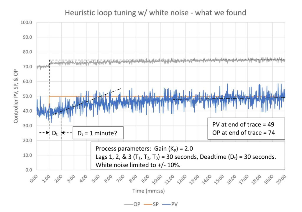
Tuning constants are K = 0.2, Ti = 3.0 minutes/repeat, Td = 0 minutes. Courtesy: Ed Bullerdiek, retired control engineer
In figure 5 we can see that noise obscures the finer details of the response to a setpoint (SP) change. This leaves us guessing at the deadtime and where the process variable (PV) and controller output (OP) ended up at the end of the trace. We are still going to calculate a baseline controller gain because it is so important to our decision-making process.
Kbase = (74 – 70)/(49 – 40)
Kbase = 0.44 (approximately)
This doesn’t look like a deadtime dominant process, which means we can be fairly confident that the controller gain is too small based on the shape of the OP response. We also suspect that the integral is too slow, but there is no need to correct that on the first tuning attempt. The normal first fix of controller gain is to raise it to at least the baseline controller gain, or 0.44.
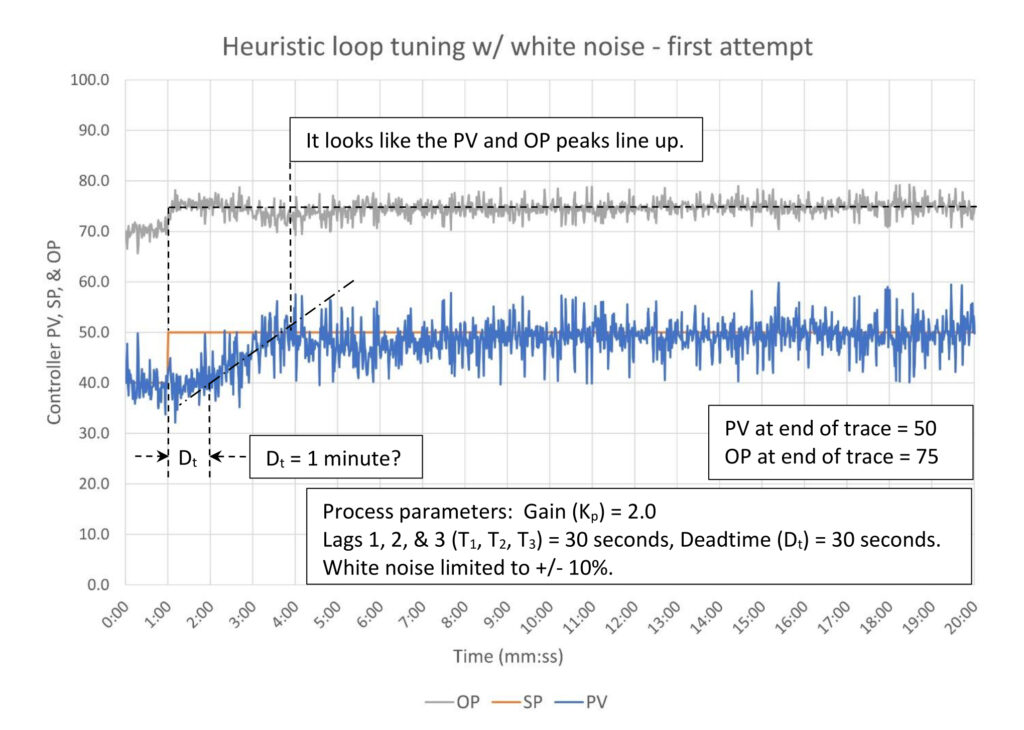
Increasing controller gain as seen in figure 6 has provided some clarity. The deadtime is still in question, but we can make a better estimate of the baseline controller gain, and we can also see that the PV looks like it reached SP before sagging. This is an indicator that the integral speed must be increased. Also, as best as we can tell there is a slight oscillation, and the PV and OP peaks line up. This looks like there might be too much controller gain for critically damped response, so we don’t want to increase controller gain much above the baseline gain. Based on these observations, we can set the controller gain to the baseline gain, and we can use the shortcut integral constant calculation to set integral.
- Kbase = ΔOP/ΔPV = 5/10 = 0.5
- The estimated integral tuning constant (Ti) is:
Ti = 2 * Dt * K / Kbase
Ti = 2 * 1.0 * 0.5 / 0.5
Ti = 2.0
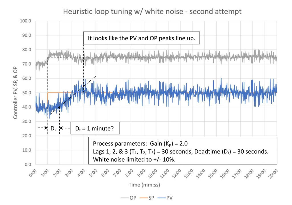
Our second attempt in figure 7 looks like we are probably about as close as we are going to get given the uncertainty the noise creates. The initial controller output response slightly overshoots the final value indicating at least minimally acceptable controller gain. There is a small oscillation after the SP change, and the peaks appear to line up. Obviously the use of derivative to straighten this out is not possible.
Noise limits our ability to fine tune controller performance by hiding the finer details of the controller response. This limits the resolution we can achieve during the tuning process. How badly might this affect the final tuning constants?
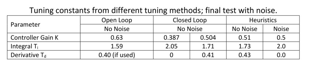
Based on Table 2 it appears that the tuning constants we developed in the presence of noise are within a reasonable range when compared to the tuning constants we developed using open, closed, and heuristic methods without noise. The controller gain is about in the middle, and the integral is about where it should be when derivative is not used.
Summary of process noise on PID controller tuning
Process noise complicates PID controller tuning. With open loop tuning noise makes it difficult to estimate the process deadtime and lag. It may require a larger controller output step to get clear results, which may not be possible if this will upset the process. Noise can make closed loop tuning much more difficult as it may take considerable time to establish a clear steady swing. This will give you more opportunity to get into trouble and may lower your ability to see it coming. Relay tuning is almost impossible with more than just minor process noise. Finally heuristic tuning is only complicated by your ability to discern the difference between process noise and the true process response. Fine details will get covered up by the noise, which means that your final tuning constants will be, at best, approximations of the optimal tuning constants.
The obvious answer to these problems is filter first and then tune. If after tuning is complete you find that you have perhaps added too much filtering, you can reduce the filter and tune again. One of the themes of this series is that controller tuning is an iterative process; setting the filter just becomes another part of the iterative process.
Ed Bullerdiek is a retired control engineer with 37 years of process control experience in petroleum refining and oil production. Edited by Mark T. Hoske, editor-in-chief, Control Engineering, WTWH Media, [email protected].
Keywords
Proportional-integral-derivative, PID tutorial
Learning objectives
- Understand how noise affects the four principle tuning methods.
- Know that when noise is present tuning usually takes longer.
- Know that noise introduces uncertainty into the tuning constant calculations. Understand that you should enter conservative tuning constants (less gain, slower integral) in the PID controller.
- Know that you should set a noise filter before tuning.
Consider this
Good PID controller tuning requires a clear picture of how the process responds. When noise muddies up that picture can we still tune?
PID series from Ed Bullerdiek, retired control engineer
Part 1: Three reasons to tune control loops: Safety, profit, energy efficiency
PID spotlight, part 2: Know these 13 terms, interactions
PID spotlight, part 3: How to select one of four process responses
PID spotlight, part 4: How to balance PID control for a self-limiting process
PID spotlight, part 5: What does good and bad controller tuning look like?
PID spotlight, part 6: Deadtime? How to boost controller performance anyway
PID spotlight, part 7: Open-loop tuning of a self-limiting process
PID spotlight, part 8: Closed-loop tuning for self-limiting processes
PID spotlight, part 9: Heuristic tuning for a self-limiting process (part A on heuristic tuning)
PID spotlight, part 10: Heuristic tuning in a self-limiting process
PID spotlight, part 11: How a PID controller works with an integrating process
PID spotlight, part 12: What does good and bad controller tuning look like?
PID spotlight, part 13: Deadtime: what’s the best that I can do?
PID spotlight, part 14: Open loop tuning of an integrating process
PID spotlight, part 15: Open loop tuning of near integrating processes
PID spotlight, part 16: Closed loop tuning of an integrating process
PID spotlight, part 17: Heuristic tuning of an integrating process
PID spotlight, part 18: Identifying control valve performance problems
PID spotlight, part 19: PID controller tuning mechanics
PID spotlight, part 20: How to tune with sticking control valves
PID spotlight, part 21: Noise: Can I tune around it?
Coming soon… PID spotlight, part 23: Filtering noise for better PID control
More on PID and advanced process control from Control Engineering