How do I prepare for a new unit startup? How do I manage tuning during the startup? What should I do after startup?

At some point in your career you will have the opportunity to start up a new process. You will be asked to tune 25, 50, or more proportional-integral-derivative (PID) controllers in a 12-hour shift. This may continue for several days. Providing custom tuning to each controller under these circumstances is not possible; you will be doing much more than just tuning loops (Why won’t that controller go in auto? Oops, the valve moved the wrong way!!) You need a way to get some kind of tuning in place quickly that will provide at least rudimentary control.
As always, proper planning prevents poor performance. This means getting reasonable controller tuning in place as soon as possible, preferably before startup. When and how can we get controllers tuned before startup?
- Before design by the selection of smart defaults.
- During control scheme design (don’t make a controller work harder than it has to; employ feedforward or other techniques to make a controller’s job easier).
- Using dynamic process models.
- Pre-commissioning subsystems where possible.
Nor should we ignore fixing valve problems before startup as these are the biggest source of controller performance problems that doesn’t involve tuning. Finally, verify controller direction before placing a controller in auto.
Implementing smart defaults
As a matter of good practice every facility should maintain a library of standard code elements. These could be full control elements (a flow controller, temperature controller, etc.), partial elements and the building blocks to more complex control schemes (cascades, ratios, etc.) These, of course, should be fully documented including implementation examples. The various controller templates should be loaded with default tuning constants. This ensures that every project whether it includes five or five hundred PID controllers starts with appropriate defaults.
Suggested defaults for the classical PID algorithm are (Table 1):

Fixing the design
Process design engineers do not think about process dynamics. It’s not in their field of expertise and they do not have to live with the results. Since it will be your fault if the controls do not work on startup it becomes your responsibility to weed out impossible control situations starting in the design process.
Get yourself involved in the design process early, preferably at the beginning of front end engineering design (FEED). Project teams generally do not involve control staff soon enough in the process, which can allow poor decisions to become baked into the design. Do not be afraid to invite yourself to early design meetings. (I learned to watch all communications from the Engineering department and stick myself into projects early.)
Remember that deadtime is the enemy. Deadtime is created by transport delay. Poor placement of valves or instruments is a leading cause, for example placing a compressor surge control valve on a platform far from the compressor. Another problem is the failure to supply a fast loop for an analyzer or simply placing the analyzer far from the process point being measured. Pay attention to plot plans and you may need to dig into selected piping drawings.
Sometimes deadtime is inherent to the process, for example in reaction control. The feed enters a large reactor with a long reaction time, after which some critical measurement is made. In these cases special attention must be paid to front end control design to minimize disturbances to the process. This can be in the form of ratio controls for reactor feed streams or feedforward/feedback schemes for reactor temperature control.
Pay careful attention to process interaction. Of particular concern are recycle processes. Examples include the recycle of unused reactants from a reactor or heat recovery schemes. These provide a means to transport an upset from the back of the process to the front. In refining we frequently avoid aggressive tuning and will often accept slow tuning to avoid causing swings because recycle paths will carry that swing back to the front of the process. You usually cannot change the process design, but you can identify where special tuning may be required and where interaction breaking feedforward controls may be required.
Another source of interaction is in complex flow systems. Flow headers and systems with blowers that include pressure and flow controls (such as heaters) can be very tricky to tune due to internal interaction. Tuning measures to avoid setting up internal resonance and priority tuning (who needs tight tuning; who can be a little sloppy) are used to limit undesired interaction.
Tuning based on dynamic process models
As processes and the controls used to control them grew more complex during my career it became necessary to build dynamic models to validate logic. These were low to medium fidelity models built with just enough detail to fully validate the logic in question and would rarely include the full process. For example only the reaction controls would be modeled on a Sulfur Recovery Unit (SRU) or feed balancing controls on a two train hydrotreater. Dynamics would be guesstimated from flow rates and process and instrument diagrams (P&ID’s). Where it was important blower and pump curves would be included, especially where there were concerns about available pressure drop or optimizing variable speed drive systems.
Naturally the controls on these models would have to be tuned. What was surprising was how well the tuning transferred to the real process. Most of the time the controller tuning would have to be trimmed after startup, but the tuning would get us through startup. And sometimes the tuning would be spot on.
The lesson here is it doesn’t require a high priced high fidelity process model to get startup tuning. Targeted modeling of critical controllers and complex schemes can greatly speed a process startup. (These simple models were also used to verify operating procedures and train operators. We also changed controls when we found out that the proposed controls simply wouldn’t work. Finding and fixing these problems before we had anxious managers staring over our shoulders was well worth the extra effort to build the models.)
Precommissioning subsystems
Projects rarely have a lull between the conclusion of instrument commissioning and startup. Usually you are still commissioning the last instruments as the unit is getting inventoried and warmed up. However, if you are in the happy situation where there are a few days to get creative do not let them pass you by.
Air handling systems should be your first priority. These systems are notorious for surprises during startup. Amongst our examples are:
- Finding, much to our surprise, that the surge curves for air blowers were wrong. That’s how we learned just how loud a surging blower can be (very loud!) This required a late control logic change to address the new estimated curve and to speed response to demand changes.
- Finding that pressure transmitters for a balanced draft heater had an unacceptable drift problem. This required a field redesign to incorporate special low draft range pressure transmitters. This would have delayed startup about one week.
- On the same heater we found binding problems on the draft dampers. This was not unexpected as this is a common problem. However it was nice to be able to work on the dampers while standing on the top of a cold heater.
- All of the air flow, cell pressure, forced draft (FD) and induced draft (ID) fan pressure controllers were tuned. This is a series-parallel arrangement of controls that all have similar dynamics. Special attention to tuning and the use of advanced PID features were required to prevent interaction induced oscillation. This was a time-consuming exercise best done outside of startup.
- We used compressed air to test the heater fuel gas controls. The heater has special startup controls that are only used during burner light-off. This permitted tuning them as we could make multiple “starts”, which would never be possible during an actual heater startup.
After this there will be opportunities to get preliminary tuning completed while the process is getting inventoried and initial circulation begins.
Validating Control Valves
The normal commissioning process for a new control valve includes a five point step check. Figure 1 shows one of the things we discovered quite by accident during the commissioning of a major process unit: A control valve can pass the standard five point commissioning test and still have serious performance problems.
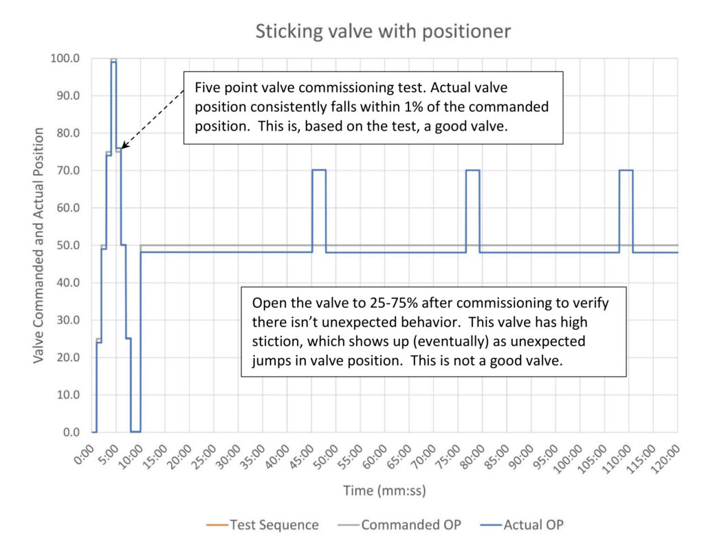
The five point test is run from the 1 to 8 minute portion of figure 1. The valve is commanded to 50% at the 10 minute mark. The actual position is a couple of percent short of 50 and the positioner is working to get the valve to 50%. The large stick limit of 23% results in a large overshoot, which when the positioner attempts to correct this the valve overshoots again. In the real world you will not get behavior that is this regular, but there will be large jumps in the actual valve position. (This is another reason to trend actual valve position if you use HART or digital instruments. Otherwise you will find these problems during startup, which will involve nervous managers staring over your shoulder.)
This behavior seems to be most common in large valves that have output boosters due to the large size of the actuators. It became a project standard to open the valve after the commissioning was complete to ensure that the valve actually is working properly. (There is no getting around it – this was unexpected and just weird.)
Commissioning controllers during startup
It’s zero-dark 30 on feed in day and if you are lucky you have your second cup of coffee in front of you. From when feed goes in until your relief arrives the day will feel like being trapped in a barrel while rolling downhill during a Wall Street panic and you are expected to solve the last three Sunday Times crossword puzzles simultaneously. It’s going to be mildly intense.
As feed cascades through the unit your job will be to verify that each controller is commissioned as needed. A controller is considered to be commissioned when it is in auto and initial tuning is complete. Presumably all the logic bugs were found and fixed during software testing and all the instruments and valves are working (don’t bet on this). You will not have time to provide final tuning for any controller nor is this recommended. Startup situations will not let you do a proper loop test as the system is nowhere close to steady state. Furthermore even if you could do a proper test you will not get good results. You must wait until the process is up and running at design pressures, flows, and temperatures before you can do final tuning. This means that we only need to provide temporary tuning that will keep the process stable.
The first step of the commissioning process is to verify controller direction. This should have been verified for all controllers long before startup but given how quickly things can go bad it is always best practice to verify controller direction before putting anything in auto. Remember that:
- Direct acting: When the process variable goes up the valve should open.
- Reverse acting: When the process variable goes up the valve should close.
Your commissioning priorities are:
- Mass balance controllers; levels and some pressures. These are controllers that cannot be left in manual.
- Flow controllers. These are often cascade secondaries (and they are quick to commission).
- Temperatures, especially where energy balances are important, and any remaining pressure controllers.
Particularly slow controllers can often be placed on hold until the process gets close to normal conditions. Obviously if it is a critical controller tune it when it first becomes available, but one of the reasons to avoid these controllers is slow controllers can be time consuming.
Naturally commissioning will be affected by when controllers become available.
At this point you may keep notes on tuning, but there’s little need to keep a formal loop tuning log. This can be a little time consuming and you will be coming back to these controllers later.
Commissioning flow controllers
Most flows will be stable with default tuning and they are always reverse acting. Assuming proper default tuning constants have been used normally you can place the controller in auto and give it a setpoint step test. If the flow is noisy set the filter to 6-10 seconds. If it shows signs of instability apply heuristic tuning rules (most likely you will cut controller gain in half.) If there is a limit cycle due to a sticking valve it is likely best to make a note and move on unless it is just absolutely untenable.
Commissioning level controllers
Default tuning of a controller gain of 2 and integral of 20 minutes/repeat generally works well unless there is a special situation (e.g. high level trip protection for a compressor). Controller direction is reverse if the level is controlled by changing feed and direct if level is controlled by output flow. Noise is rarely an issue (even though signals can be noisy) and valve problems can be managed by cascading the level to a flow controller. Normal practice is to place the controller in auto and leave a trend up to monitor the controller’s performance.
Levels are notorious for having instrumentation issues. Best practice is to have an operator verify the measurement in the field at a minimum of two levels. Be aware during commissioning that the level reading may not be real.
Commissioning pressure controllers
Pressure controller tuning depends very much on the process volume; bigger system, slower tuning. This makes it impossible to set a universal default. Controller direction is very situation dependent. Your approach to tuning depends on your guess at the speed of the process. If it is fast I prefer using heuristics to get initial tuning. If it is slow it is best to try to push this off until you can dedicate some attention to it. Noise and valve (damper) issues are common problems for draft range pressure control; both are less of a problem as pressures increase.
Pressures in flow systems and liquid pressures have very similar dynamics to flow controllers. Look for nearby flow controllers as you may encounter interaction problems. This may require special tuning, the use of advanced features, or a redesign to correct.
Commissioning temperature controllers
Temperature controller tuning, like pressure, depends very much on system size. Instrument range can also come into play in high temperature systems. For example if normal reactor temperature is near 1,000°F the temperature span might be 0-1,500°F. Normal operating range might be 100°F on either side of 1,000, which makes the process gain 200/1,500 = 0.133. This translates to a baseline controller gain of 7.5. People are not accustomed to seeing these kinds of controller gains and will be reluctant to enter such a number. Be aware of this possibility and don’t be surprised if your tuning ends up with a seemingly large controller gain.
Controller direction is generally reverse for heating and direct for cooling. Noise is rarely an issue. Control valve problems should be handled by cascading temperatures to flow or pressure controllers since (at least in refining) temperatures are slow. Most temperatures can likely be pushed off until the process gets close to operating temperature.
Fast start tuning, self-limiting process
While my preference is to use heuristic tuning during startup if your preference leans toward open loop tuning here is some guidance that may help.
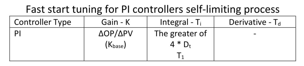
Table 2 is fast start tuning for self-limiting processes specifically for startup situations. This tuning is very slow for any process with a lag/deadtime ratio greater than 2.0, which will cover most normal processes. We want slow conservative tuning during startup because we likely have poor step test data. We don’t want to risk instability if we can help it. (Obviously if you have a controller where poor performance can result in a safety system trip or other unacceptable event take the time to tune it properly.)

Fast start PI tuning of a self-limiting process will approximate the process open loop response as can be seen in Figure 2. On the setpoint (SP) change at the 1 minute mark we can see that the process variable (PV) roughly follows the PV trajectory that would occur if we had simply opened the valve 5% (the open loop response). Obviously the controller corrects the disturbance that occurs at the 10 minute mark which wouldn’t occur if the controller is in manual.
To give you a feel for the stability margin for this tuning the ultimate gain (Ku) for a 4:1 lag/deadtime ratio process is 6.6 times the baseline controller gain (Kbase). Since the controller gain is set equal to the baseline controller gain we have a very stable controller. We may need this since we are doing step tests on an unstable process, or even just reading the trends after an operator has changed the controller output (this is a legitimate way to estimate initial tuning constants. During startup we are more often focused on speed than accuracy. Making use of available data speeds the process and doesn’t disturb a very busy operator.)
Picking the larger of the estimated primary lag or four times the deadtime helps insure the controller is stable even if it is slightly deadtime dominant (down to about a 1:2 lag/deadtime ratio). Below that you must reduce controller gain below the baseline controller gain (K < Kbase).
Fast start tuning, near-integrating process
While generally you can push off tuning slower processes during startup there may be a few that need quick tuning or you may find you have an opportunity because the operator stepped the output and created an ad hoc step test for you. This gives you a chance to apply the near integrator loop tuning process discussed in PID spotlight, part 15. Since we want quick easy tuning we can set lambda equal to ~5 times the deadtime (Dt) and simplify PID spotlight, part 15 Table 1 to what we have in Table 3:

Table 3 is the shortened lambda calculations assuming lambda is 5 times the deadtime followed by appropriate rounding. This will get you tuning that looks like Figure 3. The controller gain for this process is a little higher and the integral is slower than the open loop tuning case in Figure 2. Heuristics tells us that integral is too slow based on the process variable (PV) taking an exceptionally long time to reach setpoint (SP). This is not a concern as this will be fixed later when you come back and do your final tuning.
As the lag/deadtime ratio increases near-integrator tuning trends towards integral being too fast. This is not much of a problem for disturbance rejection, but it can make the controller response to setpoint changes oscillatory. If you think this might be a concern this can be managed by setting the setpoint filter (if your system supports this) equal to the integral constant.

After startup
Startups don’t normally have a clean end, at least not in refining. There is going to be a shakedown and discovery phase as everyone learns how the process really works and finds all the hidden features (features are not a good thing). At this point somewhere between 50 to 75% of the controllers are in service, that is in their proper mode (auto or cascade).
Barring control system issues that require your attention this is when you will start validating tuning of the controllers that are in service and commissioning any controllers that were passed over because they were slow or were exceptionally complicated (e.g. analyzers). Your tuning order should be:
- Utilities
- The process from front to back
- Cascades from bottom to top
By working from process inputs to outputs you ensure that when you tune each controller you do not have externally induced disturbances which can affect your tuning results, especially for slower controllers. By the end of this phase you should have more than 90% of controllers in service. In any larger project there are always going to be a few controllers that have issues that prevent their use. If it’s a problem that cannot be fixed then create a tuning log and note why it doesn’t work and also add a note to the logic. This will save some poor soul from having to rediscover what you have already learned.
While you are completing final tuning set up the loop tuning logs. If time is a constraint (and it always is) if you leave the default tuning in a controller you do not need to start a loop tuning log for that controller. If that controller is tuned in the future the log can be started then.
Ed Bullerdiek is a retired control engineer with 37 years of process control experience in petroleum refining and oil production. Send comments and questions to [email protected]. Edited by Mark T. Hoske, editor-in-chief, Control Engineering, WTWH Media, [email protected].
ONLINE
PID series from Ed Bullerdiek, retired control engineer
PID Spotlight, part 1: Three reasons to tune control loops: Safety, profit, energy efficiency
PID spotlight, part 2: Know these 13 terms, interactions
PID spotlight, part 3: How to select one of four process responses
PID spotlight, part 4: How to balance PID control for a self-limiting process
PID spotlight, part 5: What does good and bad controller tuning look like?
PID spotlight, part 6: Deadtime? How to boost controller performance anyway
PID spotlight, part 7: Open-loop tuning of a self-limiting process
PID spotlight, part 8: Closed-loop tuning for self-limiting processes
PID spotlight, part 9: Heuristic tuning for a self-limiting process (part A on heuristic tuning)
PID spotlight, part 10: Heuristic tuning in a self-limiting process
PID spotlight, part 11: How a PID controller works with an integrating process
PID spotlight, part 12: What does good and bad controller tuning look like?
PID spotlight, part 13: Deadtime: what’s the best that I can do?
PID spotlight, part 14: Open loop tuning of an integrating process
PID spotlight, part 15: Open loop tuning of near integrating processes
PID spotlight, part 16: Closed loop tuning of an integrating process
PID spotlight, part 17: Heuristic tuning of an integrating processes
PID spotlight, part 18: Identifying control valve performance problems
PID spotlight, part 19: PID controller tuning mechanics
PID spotlight, part 20: Tuning with bad valves
PID spotlight, part 21: Noise: Can I tune around it?
PID spotlight, part 22: Can I tune a noisy PID controller?
PID spotlight, part 23: Filtering noise for better PID control
Aug. 1 RCEP webcast available for one year: How to automate series: The mechanics of loop tuning
More on PID and advanced process control from Control Engineering